Milestone 2: SmartFollower & Tracker Mid-Point Technical Proof
This milestone documents our mid-point system for the SmartFollower & Tracker (SFT) project.
While the baseline repository demonstrates ArUco-board pose estimation from the TurtleBot 4 OAK-D camera, our current system goes beyond pose estimation and integrates:
- real-time ArUco board detection and 6-DoF pose estimation
- predicted target-goal generation for smoother following
- closed-loop robot following control with FOLLOW / LOST / SEARCH recovery
- RViz2 visualization and TF integration
- hardware deployment on TurtleBot 4 with OAK-D over ROS 2 Jazzy
This milestone is therefore not only a reproduction of the board-pose pipeline, but an extension toward a full target-tracking and smart-following stack.
0. Relation to Prior Work and Project Scope
Our implementation builds on the TurtleBot 4 OAK-D ArUco-board pose-estimation workflow.
The reference pipeline detects a known 4-marker ArUco board, estimates its 6-DoF pose, and publishes board pose, orientation, visibility, detected marker IDs, and TF.
Our project extends that baseline in three important ways:
-
Tracking-oriented outputs instead of pose-only outputs
We use the detected board pose as the perception input to a downstream tracking and following stack. -
Prediction and goal generation
Instead of commanding the robot directly from instantaneous detections only, we estimate short-horizon target motion and generate a follow goal. -
Autonomous follow behavior with recovery logic
We add a coordinator state machine with FOLLOW, LOST, and SEARCH modes to make the robot robust to temporary target loss.
This aligns the system with our broader SmartFollower & Tracker project objective: autonomous target following in a dynamic indoor environment.
1. Kinematics
The TurtleBot 4 uses a differential drive motion model. The robot state is defined as:
\[\mathbf{x} = [x, y, \theta]^T\]where \(x\), \(y\) is the position and \(\theta\) is the heading angle.
Given control inputs linear velocity \(v\) and angular velocity \(\omega\), the state update over timestep \(\Delta t\) is:
\[\begin{bmatrix} x_{t+1} \\ y_{t+1} \\ \theta_{t+1} \end{bmatrix} = \begin{bmatrix} x_t + v \cos(\theta_t) \Delta t \\ y_t + v \sin(\theta_t) \Delta t \\ \theta_t + \omega \Delta t \end{bmatrix}\]In our current mid-point system, the coordinator generates control inputs directly from the detected board pose expressed in camera frame. The control law is a proportional tracking controller embedded inside a larger perception → goal generation → coordination pipeline. These equations describe the low-level follow behavior used by the coordinator; however, the complete system also includes target detection, short-horizon prediction, and recovery behavior when the board is temporarily lost.
\[v = \text{clip}\bigl(K_{lin} \cdot (z_{board} - d_{target}),\ -v_{max},\ +v_{max}\bigr)\] \[\omega = \text{clip}\bigl(-K_{ang} \cdot x_{board},\ -\omega_{max},\ +\omega_{max}\bigr)\]where \(z_{board}\) is the board depth (distance from camera), \(x_{board}\) is the lateral offset, and the controller parameters are:
| Parameter | Value | Description |
|---|---|---|
| \(d_{target}\) | \(0.65\) m | Desired follow distance |
| \(K_{lin}\) | \(0.8\) | Proportional gain for linear velocity |
| \(K_{ang}\) | \(2.0\) | Proportional gain for angular velocity |
| \(v_{max}\) | \(0.15\) m/s | Maximum linear speed (forward and backward) |
| \(\omega_{max}\) | \(0.6\) rad/s | Maximum angular speed |
Errors smaller than a deadband threshold are zeroed before computing the control output, preventing jitter when the board is approximately centered:
\[z_{error} = \begin{cases} 0 & \text{if } |z_{board} - d_{target}| < 0.03\ \text{m} \\ z_{board} - d_{target} & \text{otherwise} \end{cases}\] \[x_{error} = \begin{cases} 0 & \text{if } |x_{board}| < 0.02\ \text{m} \\ x_{board} & \text{otherwise} \end{cases}\]The linear velocity is clamped symmetrically to \([-v_{max}, +v_{max}]\), allowing the robot to drive backward when the board is closer than \(d_{target}\). This prevents the robot from stalling against the target if it approaches too close.
2. System Architecture
2.1 Computational Map
graph LR
    subgraph Perception
        CAM["TurtleBot4 OAK-D\n/robot_09/oakd/rgb/image_raw/compressed"]
        DET["aruco_detector\nPublishes pose / visibility / TF / debug"]
    end

    subgraph Prediction
        GEN["goal_generator\nPredicted target goal\nand RViz markers"]
    end

    subgraph Coordination_and_Control
        COO["coordinator\nFOLLOW / LOST / SEARCH\nstate machine"]
    end

    subgraph Robot_Interface
        CMD["/robot_09/cmd_vel"]
        RV["RViz2 + TF"]
    end

    CAM --> DET
    DET --> GEN
    DET --> COO
    GEN --> COO
    DET --> RV
    GEN --> RV
    COO --> RV
    COO --> CMD
RQT graph:
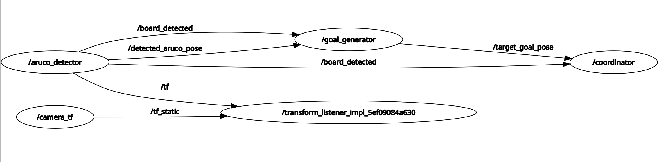
Topics:
| Topic | Message Type | Publisher | Subscriber / Consumer |
|---|---|---|---|
/robot_09/oakd/rgb/image_raw/compressed | sensor_msgs/msg/CompressedImage | TurtleBot 4 OAK-D | aruco_detector |
/detected_aruco_pose | geometry_msgs/msg/PoseStamped | aruco_detector | goal_generator, coordinator |
/board_detected | std_msgs/msg/Bool | aruco_detector | goal_generator, coordinator |
/aruco_debug_image | sensor_msgs/msg/Image | aruco_detector | RViz2 |
/aruco_markers | visualization_msgs/msg/MarkerArray | aruco_detector | RViz2 |
/target_goal_pose | geometry_msgs/msg/PoseStamped | goal_generator | coordinator |
/goal_generator_markers | visualization_msgs/msg/MarkerArray | goal_generator | RViz2 |
/coordinator_state | std_msgs/msg/String | coordinator | RViz2 / logs |
/coordinator_markers | visualization_msgs/msg/MarkerArray | coordinator | RViz2 |
/robot_09/cmd_vel | geometry_msgs/msg/TwistStamped | coordinator | TurtleBot 4 base controller |
/tf | tf2_msgs/msg/TFMessage | aruco_detector | RViz2 / TF tools |
2.2 Module Descriptions
Module Declaration Table:
| Module | Type | Status | Role in System | Source File |
|---|---|---|---|---|
aruco_detector | Custom | Completed | Detects 4-marker board, solves 6-DoF pose, publishes TF and debug outputs | aruco_detector.py |
goal_generator | Custom | Completed | Predicts short-horizon target motion and publishes follow goal | goal_generator.py |
coordinator | Custom | Completed | Executes FOLLOW / LOST / SEARCH state machine and robot command output | coordinator.py |
| OAK-D camera topic interface | System | Completed | Provides compressed RGB stream from TurtleBot 4 | TurtleBot 4 stack |
| Static TF / frame setup | System | Completed | Provides frame consistency for visualization and integration | launch/config |
| RViz2 visualization | System | Completed | Displays detections, goals, and controller state | RViz2 config |
aruco_detector
This module is the perception front end of the system. It subscribes to the TurtleBot 4 OAK-D compressed RGB topic and decodes each compressed frame using cv2.imdecode for OpenCV ArUco processing. Using the configured 4-marker board geometry and camera calibration, it estimates the board pose with solvePnP. The core detection and pose computation methods are based on board_pose_ros implementation, which was tested and validated on real TurtleBot 4 hardware.
Implemented functionality includes:
- compressed image subscription and decoding via
np.frombuffer+cv2.imdecode - 4-marker board detection using
cv2.aruco.detectMarkersdirectly withDICT_6X6_250 - board object point construction via a 2D rotation matrix applied per-marker (not corner reordering)
- 6-DoF board pose estimation in camera frame using
solvePnP - robust quaternion conversion from rotation matrix using a 4-case singularity-safe method
- RPY extraction from rotation matrix with singularity handling
- exponential moving average smoothing (
alpha = 0.25) - board visibility reporting
- TF broadcast from
camera_frametoboard_frame - RViz2 debug image and marker visualization
Published outputs:
/detected_aruco_pose— smoothed board-center pose incamera_frame/board_detected— board visibility flag/aruco_debug_image— annotated image for visualization/aruco_markers— marker visualization in RViz2/tf— transform from camera frame to board frame
All values are expressed using camera-frame convention: +X = right, +Y = down, +Z = forward.
goal_generator
This module currently serves as a placeholder passthrough in the mid-point system. In its present form, it forwards the /detected_aruco_pose topic directly to /target_goal_pose with minimal processing, allowing the coordinator to function end-to-end on hardware while the full prediction backend is being integrated. This placeholder will be replaced by Prajjwal’s state estimation and prediction stack for the final system.
Planned Replacement: State Estimation and Prediction System done in the Simulation
The production goal generator will be grounded in a rigorous probabilistic state estimation framework that is developed independently as part of the broader project. Rather than simply forwarding the last detected pose, the replacement module applies a multi-filter sensor fusion pipeline to produce a smoothed, forward-predicted target goal.
The core of the system is an Extended Kalman Filter (EKF) operating over an 8-dimensional state vector:
\[\mathbf{x} = [x,\ y,\ \theta,\ v_x,\ v_y,\ \omega,\ a_x,\ a_y]^T\]The filter runs a prediction step at 50 Hz using a constant acceleration motion model:
\[x_{t+1} = x_t + v_x \Delta t + \tfrac{1}{2} a_x \Delta t^2, \quad y_{t+1} = y_t + v_y \Delta t + \tfrac{1}{2} a_y \Delta t^2, \quad \theta_{t+1} = \theta_t + \omega \Delta t\]This prediction step propagates the state forward between measurements, maintaining continuous estimates even when the ArUco board is temporarily undetected. When new pose observations arrive from the detector, the EKF performs a measurement update via the standard Kalman gain formulation, weighting each correction by the relative uncertainty of the model and the sensor.
Beyond the EKF, the simulation implements two additional filter variants for comparison and robustness evaluation: an Unscented Kalman Filter (UKF), which propagates deterministically chosen sigma points through the nonlinear motion model to capture higher-order distribution moments without requiring explicit Jacobian computation, and a Particle Filter (PF), which represents the full posterior distribution over target state using a weighted set of 500 particles and handles multi-modal or highly non-Gaussian scenarios through systematic resampling. The three filters run simultaneously on the same sensor stream, and their outputs are visualized side by side to identify which method best tracks the target in the current operating environment.
For the final integration, the selected filter output — most likely the EKF for its efficiency or the UKF for its accuracy on smooth trajectories — will drive the follow-goal computation. The predicted future target position at a configurable horizon \(t_{\text{predict}}\) will be computed directly from the filter state:
\[\text{pred} = \mathbf{p}_{\text{current}} + \mathbf{v}_{\text{estimated}} \cdot t_{\text{predict}}\]A stand-off offset will then be applied along the depth axis to produce the final /target_goal_pose, ensuring the coordinator targets a point at a safe following distance rather than the board center itself.
This replacement will substantially improve following smoothness, reduce reaction lag during target acceleration, and enable the coordinator to maintain a valid goal estimate during short occlusion events — directly addressing the primary limitation of the current passthrough approach.
coordinator
This module is the behavior and control layer of the mid-point system. It consumes board visibility and target-goal information and commands the TurtleBot 4 through a three-state recovery-aware controller:
- FOLLOW: track the target using proportional distance and heading control
- LOST: stop the robot and wait briefly for re-detection
- SEARCH: wait and do something for the target to be re-acquired
State transitions are driven by board visibility and timeout logic.
At mid-point, this gives the system a practical target-following capability with basic robustness to occlusion and intermittent perception failure.
The coordinator publishes:
TwistStampedcommands to/robot_09/cmd_vel- textual state information on
/coordinator_state - visualization markers on
/coordinator_markers
This module is the main step that moves the project from “board pose estimation” to “autonomous smart following.”
3. Experimental Analysis & Validation
At this milestone, our validation focus is to show that the core SmartFollower & Tracker pipeline is working end-to-end on hardware: perception, target-goal generation, robot following, target-loss recovery, and visualization. Full project goals such as obstacle avoidance in dynamic warehouse settings and 2D reconstruction are part of the broader final-system scope and are not yet fully claimed in this milestone.
3.1 Sensor Calibration
Camera intrinsic calibration was performed using a chessboard pattern (camera_calib_oak.npz). The calibration provides the camera matrix and distortion coefficients used by solvePnP for accurate 3D pose estimation.
Board extrinsic calibration is defined in board_config.json, which specifies the physical top_left_xy_m position of each marker relative to the board center. The marker size is 0.0225m and the board uses DICT_6X6_250.
3.2 Coordinate Frame Convention
All pose values are expressed in camera frame:
| Axis | Direction | Used for |
|---|---|---|
+X | Right of camera center | Steering (angular_z) |
+Y | Below camera center | Not used for control |
+Z | Forward (depth) | Driving (linear_x) |
For this milestone implementation, the camera frame is used as the primary operational reference for perception and short-horizon following. A static TF alignment is used for visualization and integration convenience, but this should not be interpreted as a full global localization solution.
3.3 Run-Time Issues & Recovery
| Issue | Observed Behavior | Recovery Logic |
|---|---|---|
| Board temporarily occluded | Pose age exceeds 0.5 s timeout; robot stops immediately | FOLLOW → LOST after 5 s of board_visible = False |
| Board lost for >5 seconds | Robot stops in LOST state | LOST → SEARCH after timeout |
| Board not found during search | Robot stops and waits in SEARCH state | SEARCH resets timer after 30 s |
| VMware USB passthrough instability | OAK-D disconnects on boot | Subscribe to ROS2 topic over WiFi instead |
| QoS mismatch | RViz2 Image display shows “No Image” | Publisher set to BEST_EFFORT, RViz2 set to match |
3.4 What We Added Beyond the Reference Repository
The reference TurtleBot 4 OAK-D ArUco-board repository provides the perception baseline: compressed image subscription, board detection, pose estimation, orientation output, visibility output, detected marker IDs, and TF.
Our milestone system extends beyond that baseline by adding:
- smoothed board-pose tracking for downstream control
- predicted target-goal generation from recent motion history
- a robot-following coordinator state machine
- LOST / SEARCH recovery behavior
- integrated RViz visualization for detection, goals, and controller state
- hardware-tested end-to-end following behavior on TurtleBot 4
Therefore, this milestone should be presented as an extension of prior board-pose work into a smart-following system, not just as a reimplementation of the pose-estimation package.
3.5 Demonstration Videos
Below are three short hardware demonstration videos showing the SmartFollower & Tracker system running on the TurtleBot 4 and simulation. The videos highlight the perception, prediction, and hardware implementation of the robot.
-
Aruco tracking + Robot state switching YouTube Video 1
Real‑time board detection, board position and robot state visualization. -
Hardware implemented Target follower YouTube Video 2
Turtlebot following Arucho board in view. -
Target tracking + prediction simulation YouTube Video 3
Simulation of robot tracking a target with EKF.
4. Project Management
4.1 Instructor Feedback Integration
| Instructor Critique / Question | Technical Action Taken |
|---|---|
| Is your test environment going to be the lab space? If so, how are you going to recreate the dynamic factory/warehouse setting? You could also use a simulation environment. | Our hardware validation uses the lab space, where a person carries the ArUco board at varying speeds, changes directions, and temporarily occludes it to exercise the FOLLOW, LOST, and SEARCH recovery states. For controlled dynamic scenarios, the simulation space provides a structured environment where a leader robot navigates autonomously while the follower tracks it, allowing repeatable testing of occlusion, target acceleration, and obstacle interaction without depending on lab availability. |
4.2 Individual Contribution
| Team Member | Primary Technical Role | Key Git Commits/PRs | Key Contributions |
|---|---|---|---|
| Tatwik Meesala | Perception and integration | 7646c12 | board detection pipeline, SolvePnP integration, image transport handling, hardware testing |
| Prajjwal | Prediction and mapping-oriented system development | 38f644f | future-position estimation, follow-goal generation, broader SLAM / reconstruction direction |
| Lu Yan Tan | Coordination, control, and visualization | a676342 | FOLLOW / LOST / SEARCH state machine, TF / RViz integration, robot command behavior |
5. Mid-Point Status Summary
By Milestone 2, we have demonstrated a working hardware pipeline that:
- detects a known 4-marker ArUco board using the TurtleBot 4 OAK-D camera
- estimates the board pose in real time
- predicts short-horizon target motion
- generates a follow goal
- commands the robot through a recovery-aware FOLLOW / LOST / SEARCH controller
- visualizes the system in RViz2 with TF support
This confirms that the project has progressed beyond pose-only perception and now includes the core behavior required for a SmartFollower & Tracker system. The remaining project scope focuses on expanding robustness, safety behavior, obstacle interaction, and reconstruction-oriented outputs toward the final system objective.